7 Pin Wire Diagram : 7 Pin Flat Trailer Plug Wiring Diagram | Trailer Wiring ... - I found mistakes in text books where for argument sake they had the resistor colouring codes mixed up!. The ds18b20 has four main data components: Pins 1 & 2 (green) and pins 3 & 6 (orange) are used for data communications while pins 4 & 5 (blue) and pins 7 & 8 (brown) are not used. This is the standard uk wiring of a the supplementary socket and plug otherwise known as 12s. Each component should be set and connected with other parts… Don't try yellow to yellow and green to green this is what you'll need to know if you ever want to tap into the wires that feed the 7 pin connector.
3.1.3 wiring the power line. Trailer wiring diagram, trailer brake light plug wiring diagram, electric trailer brakes, hitch lights, 7 pin, 7 way, 7 wire, 6 pin, 6 way, 6 wire, 4 pin, 4 way, 4 wire, connector, connection, utility, horse, cargo, motorcycle, snowmobile, car, travel, rv. There have been slight variations over the years as most. It shows the components of the circuit as simplified shapes, and the power and signal connections between the devices. Looking at trailer wiring harness diagrams, i see that a seven pin harness has a pin, usually wired black, that is described as 12v battery.

It will if anything give you the right idea to figure out.
Each component should be set and connected with other parts… Some trailers come with different connectors for cars and some have different wiring styles. I did make the correction in the book and told the librarian as this confuse the beginners. There have been slight variations over the years as most. It will if anything give you the right idea to figure out. Pins 1 & 2 (green) and pins 3 & 6 (orange) are used for data communications while pins 4 & 5 (blue) and pins 7 & 8 (brown) are not used. Second signal pin to controller pin socket 3 (in circuit diagram). This is the style we recommend. The following trailer wiring diagram(s) and explanations are a cross between an electrical schematic and wiring on a trailer. If so, does it have power when the ignition is off, or only when on? This article shows 4 ,7 pin trailer wiring diagram connector and step how to wire a trailer harness with color code ,there are some intricacies involved in wiring a trailer. 3.1.2 connectors and terminals of nc300 controller. Caravan 12s wiring diagram, showing fridge, battery charging, live & reversing light connections as well as the cable sizes from western towing.
This type of connector is normally found on utvs, atvs and trailers that do not have their own braking system. See the table below for pins of the mlc (x0~27/y0~27): This is the style we recommend. Looking at trailer wiring harness diagrams, i see that a seven pin harness has a pin, usually wired black, that is described as 12v battery. Now draw a diagram showing the pins on your display.
Now draw a diagram showing the pins on your display.
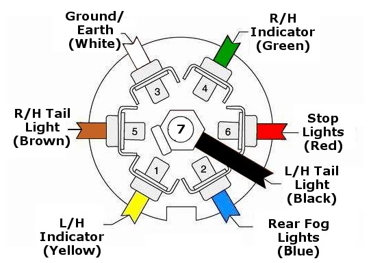
Each component should be set and connected with other parts… 7 pin trailer wiring diagram with brakes. It shows the components of the circuit as simplified shapes, and the power and signal connections between the devices. Pinout diagrams and wire colours for cat 5e, cat 6 and cat 7. An ethernet cable rj45 connector has 8 pins. There have been slight variations over the years as most. 7 pin 'n' type trailer plug wiring diagram7 pin trailer wiring diagramthe 7 pin n type plug and socket is still the most common connector for towing. It will if anything give you the right idea to figure out. Caravan 12s wiring diagram, showing fridge, battery charging, live & reversing light connections as well as the cable sizes from western towing. This article shows 4 ,7 pin trailer wiring diagram connector and step how to wire a trailer harness with color code ,there are some intricacies involved in wiring a trailer. Pin 1 pin 3 pin 5 pin 7 pin 9 pin 11 pin 13. 8 pin wiring diagram wiring diagram 500. Posted on sep 11, 2014.
How to wire an effect circuit into your guitar Posted on sep 11, 2014. This is the standard uk wiring of a the supplementary socket and plug otherwise known as 12s. Some trailers come with different connectors for cars and some have different wiring styles. This vehicle is designed not only to travel one place to another but also to take heavy.

The wires will be different colors and pin callouts will be wrong, but the major portion is similar.
Pin pin 8pin soic to92 symbol description. Cut and strip (ground) black wire pin 24 and (+12v) yellow wire pin 11. This is the standard uk wiring of a the supplementary socket and plug otherwise known as 12s. Caravan 12s wiring diagram, showing fridge, battery charging, live & reversing light connections as well as the cable sizes from western towing. Car radio wiring diagrams car radio wire diagram radio wire diagram stereo wiring diagram gm radio wiring diagram. I drew this crude diagram to help explain. Pin 1 pin 3 pin 5 pin 7 pin 9 pin 11 pin 13. 7 pin heavy duty trailer wiring diagram. Trailer wiring diagram, trailer brake light plug wiring diagram, electric trailer brakes, hitch lights, 7 pin, 7 way, 7 wire, 6 pin, 6 way, 6 wire, 4 pin, 4 way, 4 wire, connector, connection, utility, horse, cargo, motorcycle, snowmobile, car, travel, rv. Pinout diagrams and wire colours for cat 5e, cat 6 and cat 7. I did make the correction in the book and told the librarian as this confuse the beginners. This type of connector is normally found on utvs, atvs and trailers that do not have their own braking system. An ethernet cable rj45 connector has 8 pins.